Professional articles | Blog | ARCHLine.XP
Dimensioning in ARCHLine.XP
One of the most important features of ARCHLine.XP is the dimensioning tools. The aim of the program is to speed up the dimensioning process and enable us to place accurate dimensions with just a few clicks. Let's see how.
1. Quick dimensioning
With the quick dimensioning tool, you can place the length of the selected item on the drawing with one click. The tool is perfectly suited for in-the-process, quick dimensioning, or for complementing automatic dimensions.
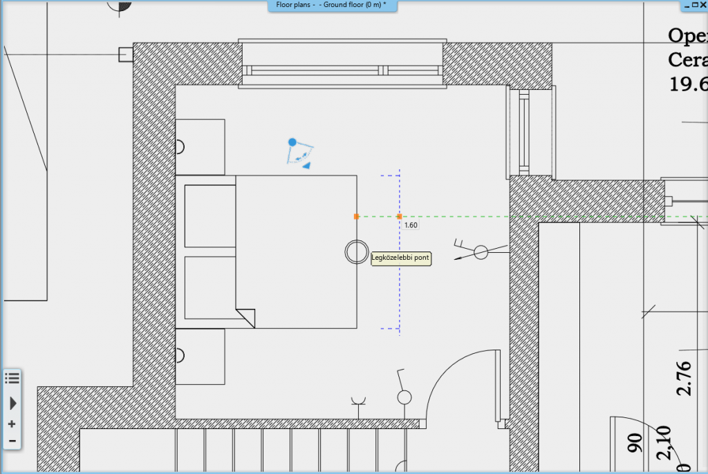
2. Length dimensioning
Length dimensioning differs from the quick dimensioning in that the program does not recognize the two endpoints of the selected item, but we can define the distance between points. Thus, it is possible to manually place dimensions of partition walls or wall thicknesses on the outside of a wall.
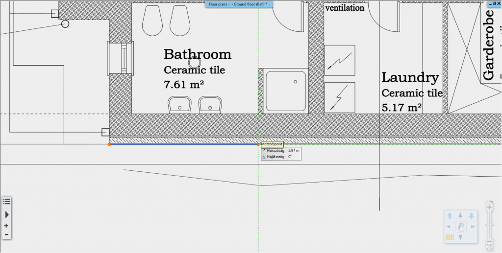
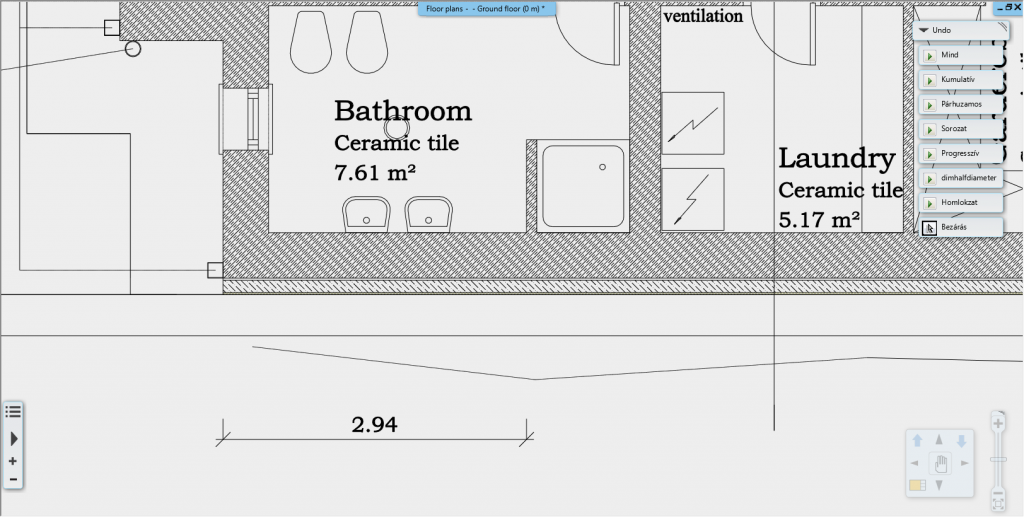
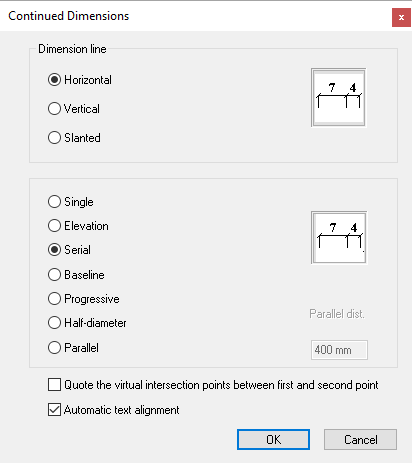
3. Serial dimensioning
Serial dimensioning is a type of length dimensioning that is designed to accelerate the placement of long series of dimension chains. In the dialog, you can select the orientation of the placement (vertical, horizontal or slanted), and select the serial option. Next, place the first dimensioning after defining the start and end points of the item. The next dimensioning is automatically placed in a row after the previous one, so you always have to define just the end point for the next item.
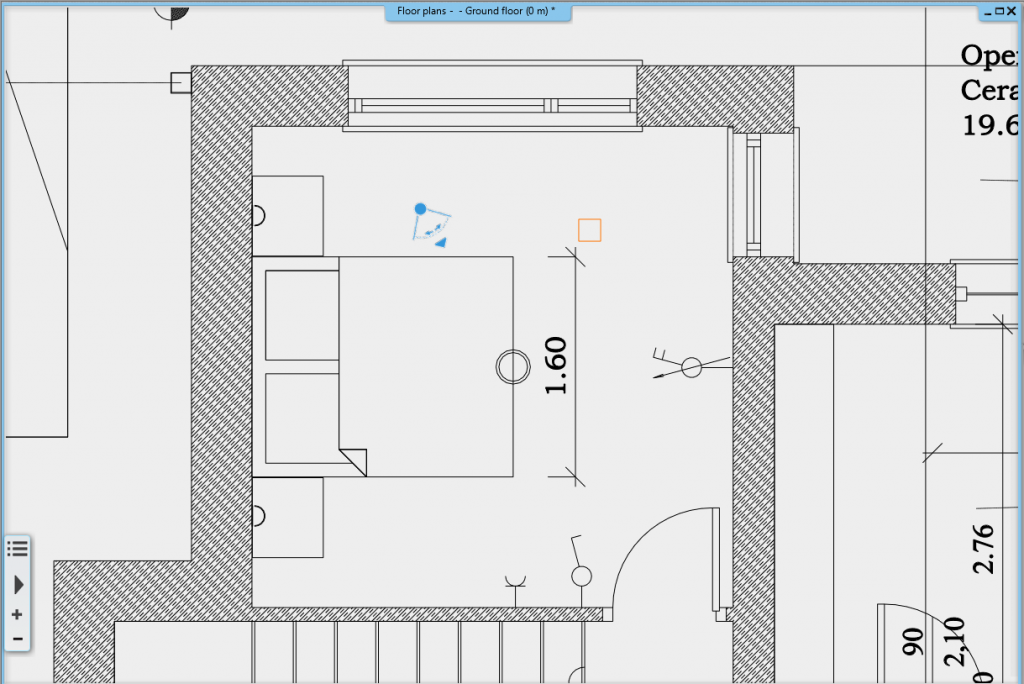
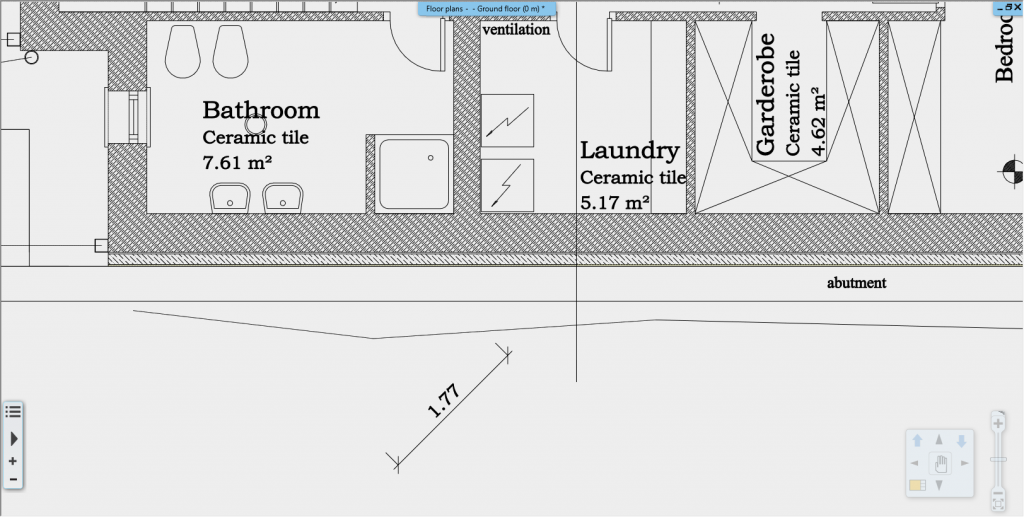
4. Lengths aligned
After you start the command, you can type in the desired angle in which you want to place the dimensioning, or you can manually adjust the position of the endpoint of the displayed orange line. Then, by clicking on the item, you can place its dimensions on the drawing at the previously specified angle.

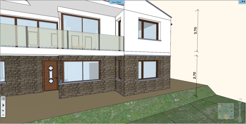
5. Dimensioning in 3D
There may be a case when we want to visualize the dimensions of an item in 3D for ourselves or for our customer. This can be done with the 3D dimensioning option. We can dimension elements by letting the program recognize its length by itself, but we can also determine the start and end point of an item in space.
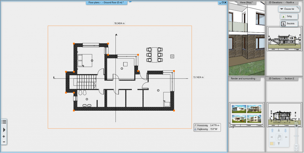
6. Dimensioning all of the walls in one step
We have the ability to preset all dimensioning and place them in a single step, saving us a considerable amount of time during the project documentation. In the dimension dialog, we can select from the pre-defined list what dimensioning types we want to place on the drawing. The order in which we add the types to the list determines which dimensioning chain will be closer to the wall. Even though the dialog contains wall dimension types, as the doors and windows are part of the walls, we can add door and window dimension types to the list, as well as the height of the sills.
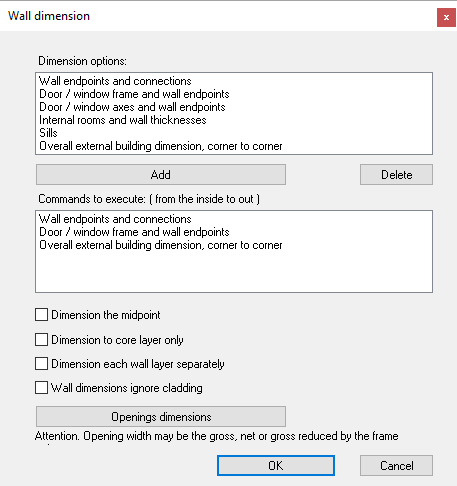
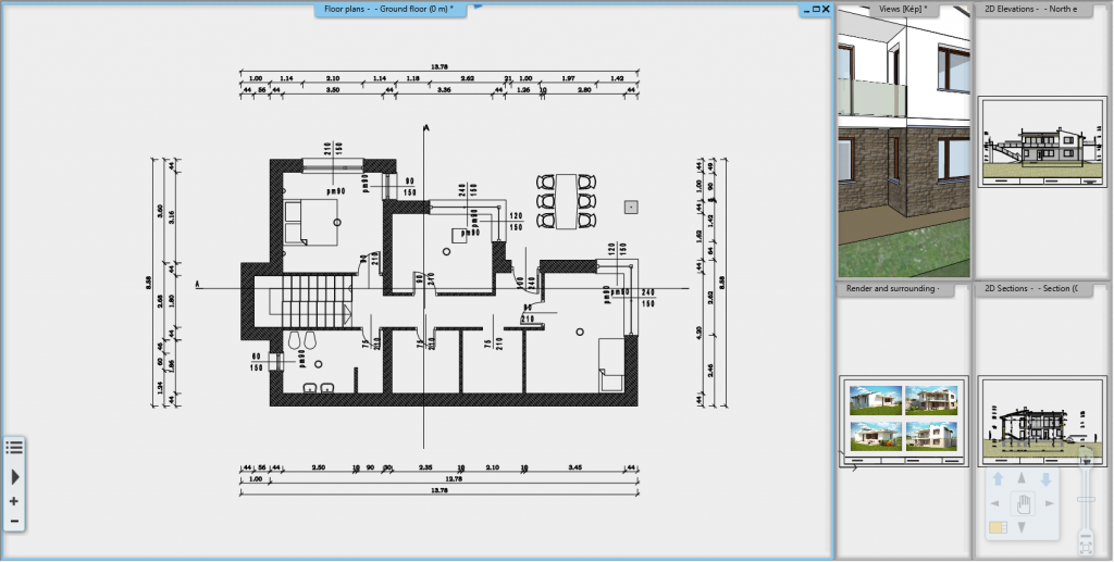
In the dialog, we can turn on special dimensioning options, such as dimensioning the wall midpoint, wall dimensions ignore to cladding, dimensioning the core layer only, or each wall layer separately.
After setting everything up, close the dialog with the OK button, then select the walls to be dimensioned one by one or with one of the selection rectangles and determine the distance of the first chain from the walls. The program then places all the dimensioning. By using this tool, we can also reduce the number of missing dimensions as the program automatically places everything.
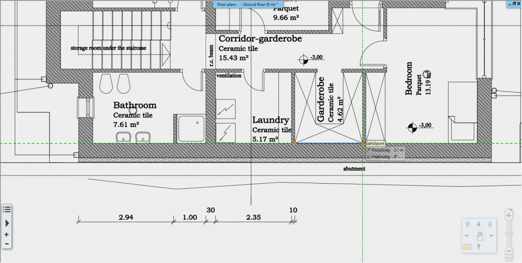
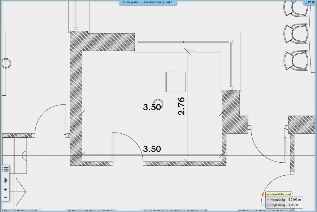
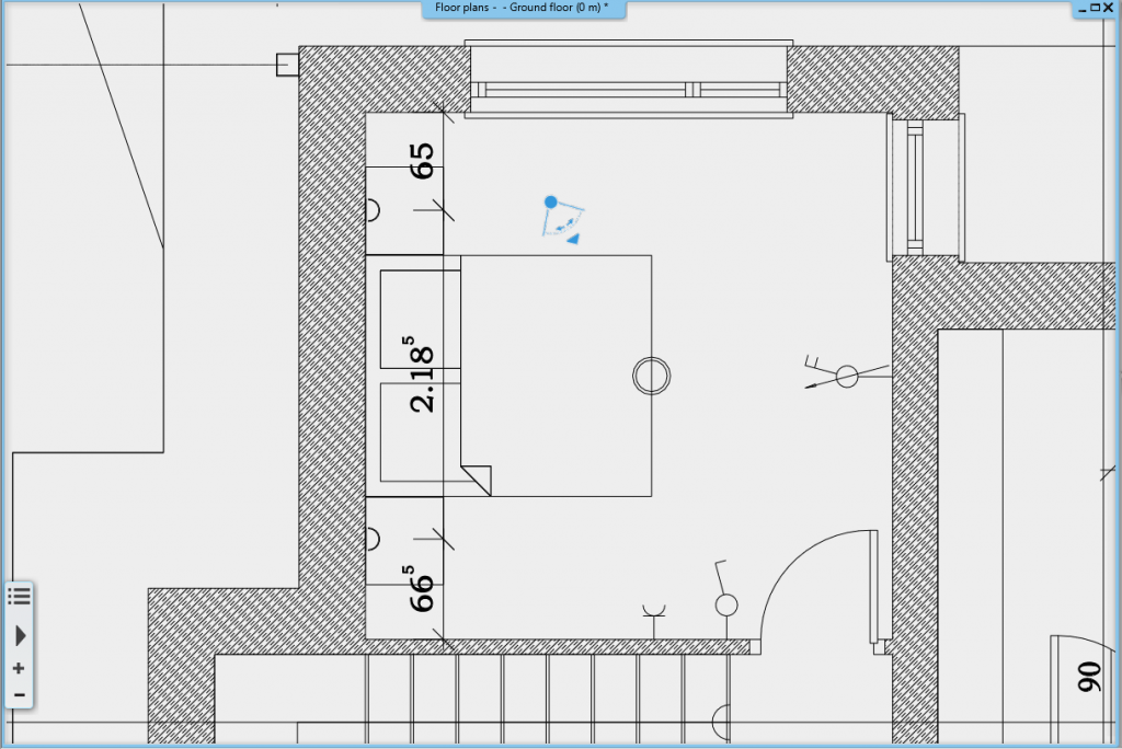
7. Room internal dimensions
The Room Internal Dimensions command instantly displays the internal distance of all the boundary walls form one another by clicking on one of the walls of the room. Using it, we can get an accurate picture of the size of our room quickly and easily.
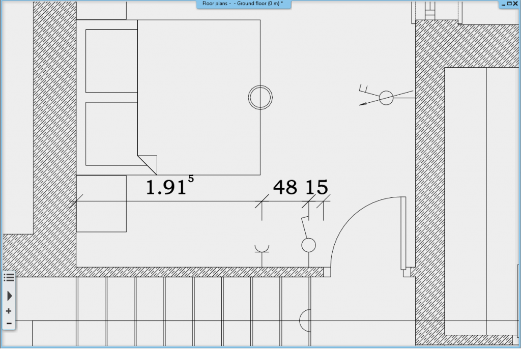
8. Switches and sockets
We can also easily dimension the switches and sockets in our project for the electrical plan. Just select the side of the wall on which we placed the electrical accessories and specify the distance of the dimensioning chain from the wall. The program automatically displays the distance between the switches/sockets and the wall corners.
We can also easily display the mounting height of the switches/sockets in our project. If we click on the All elevation command, in the appearing dialog, we can display the binding height next to all the switches/sockets in a box.
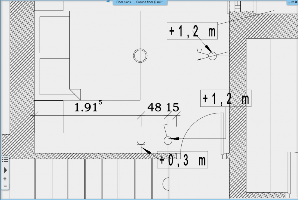
9. Lamps on wall
The dimensioning of wall lamps also works as described above. Select the wall on which our lamps are and place the dimensioning chain at a suitable distance.
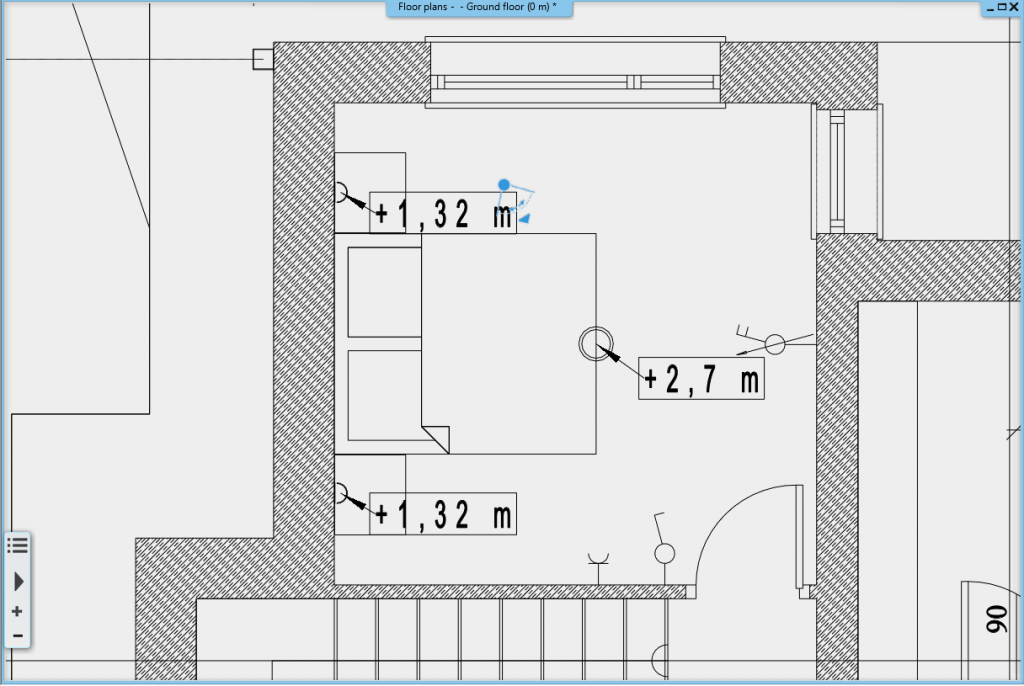
Height values are automatically displayed for all lamps on the plan, not just wall lamps. Just like in the case of the switches, the height values are displayed in a box near the lamp.
10. Cabinets
The width of the designed kitchen cabinets can be displayed using the Cabinet Dimension tool. Just select the cabinets you want to dimension, or choose Define all from the Ribbon Bar, Cabinet group. The program automatically places the dimensions.
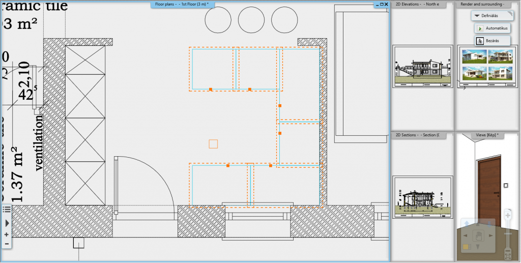
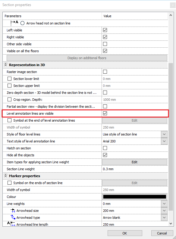
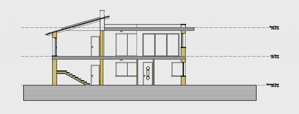
11. Display level annotation lines on section
For some sections, it may be important to display the levels. This option can be turned on in the section settings dialog. The project may contain empty levels as well - the lines of which can be easily deleted on the section.