New in ARCHLine.XP 2018
ARCHLine.XP 2018 is your Gateway to BIM
2018 user interface - the Ribbon Bar
It organizes tools into logical groups. The ribbon is composed of a series of tabs, which are organized into panels.
Relocating the whole work environment
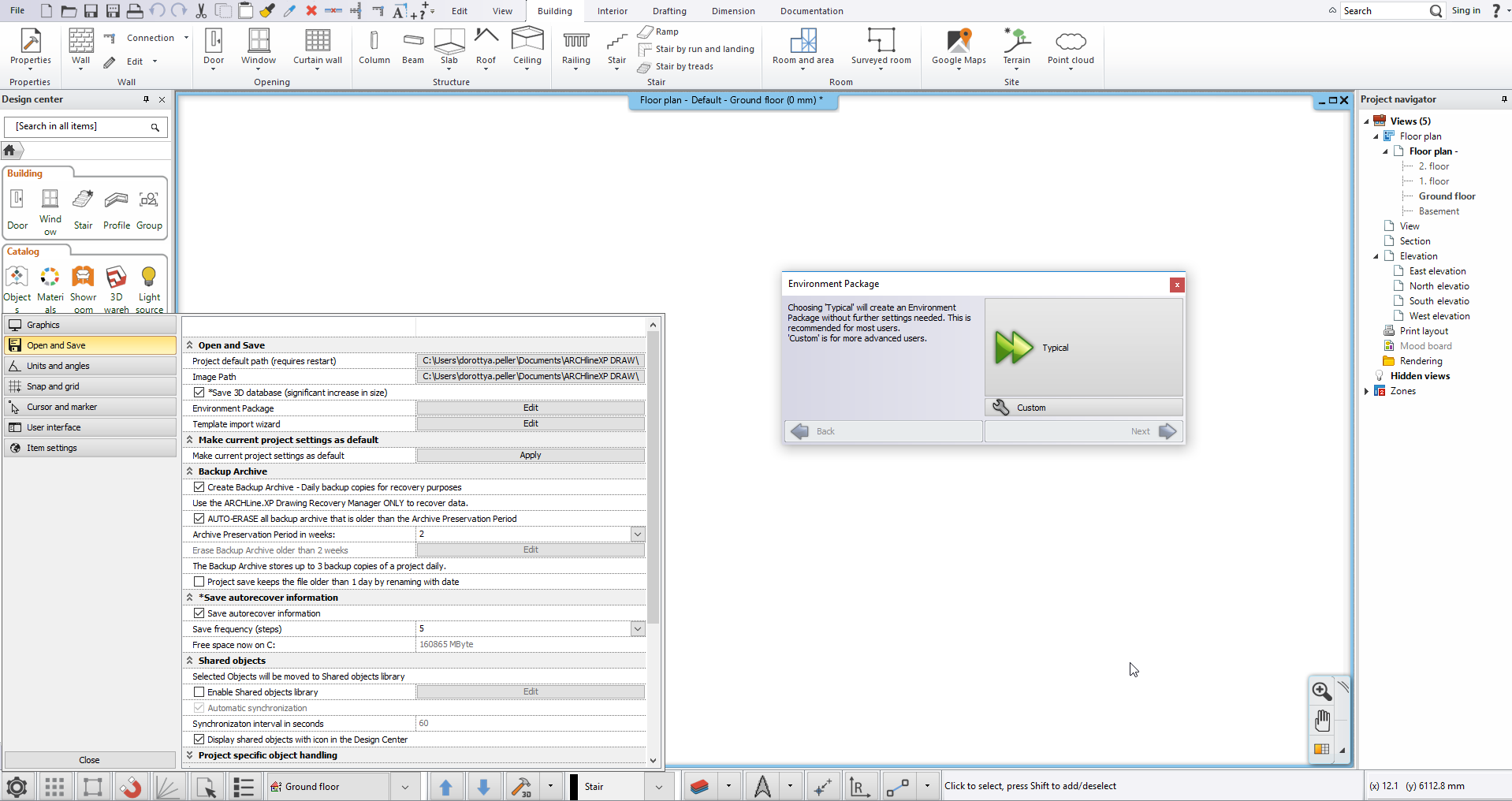
The environment relocation has new features in ARCHLine.XP 2018.
We can save and scan any user data that is supported by the program in a single file. Supported data includes the user-generated material library, style library, objects created by the user or downloaded from the internet, and all user settings (linetypes, sun settings, views).
The command is available in the Settings / Open and Save tab under the "Environment Package" button.
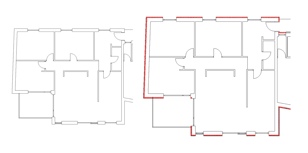
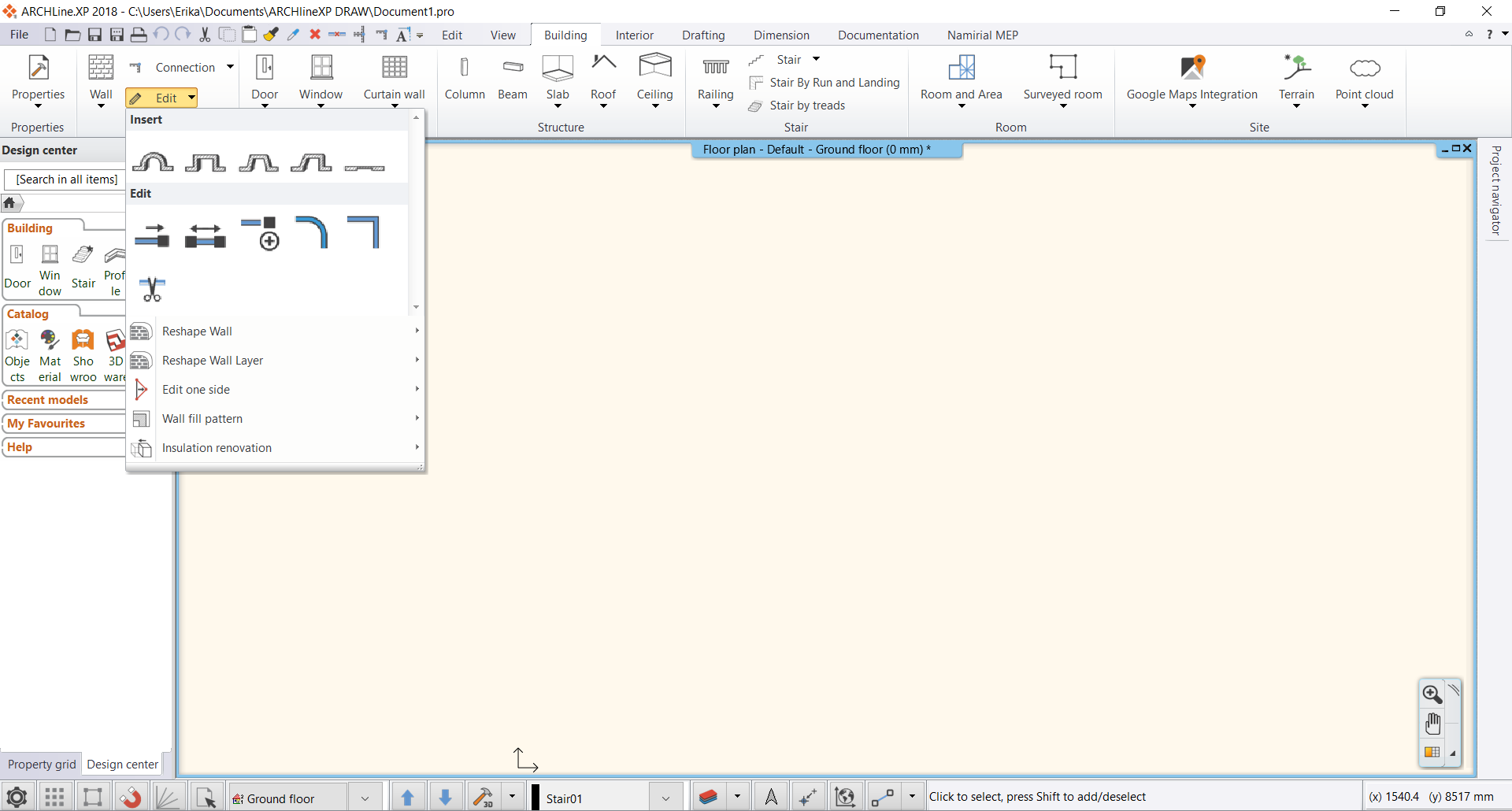
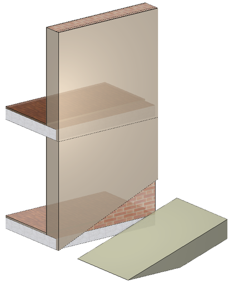
Insulation Renovation to Walls
Insulation renovation process increases the thermal efficiency of existing buildings. You can add new layers of insulation to existing walls.
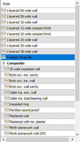
Styles directly available from the Property manager
Property Manager changed: When you start an item creating command, a list of styles will appear on the left side of the interface and if you click on the style name, the selected style become active. The item you create next is made with the properties of the new style. Thanks to this solution, you can quickly switch between styles, for example, when you draw a load-bearing wall, then a partition wall and then a load-bearing wall again.
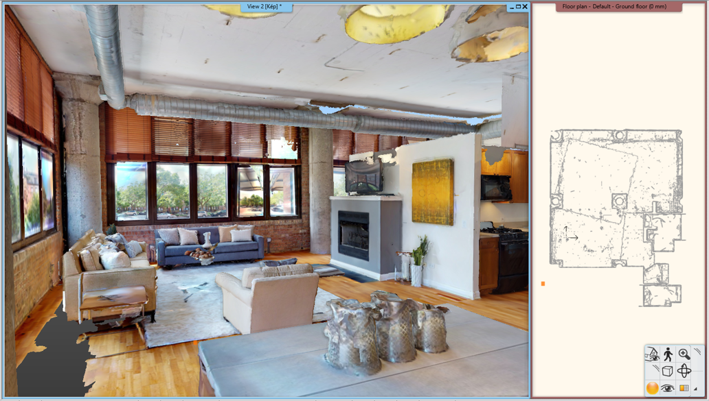
Point Clouds
The Point Cloud is made with laserscanners to capture building and environment dimensions.
ARCHLine.XP imports point cloud files to support the design process by providing real-world context.
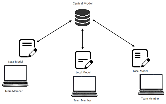
Enhanced Teamwork
ARCHLine.XPsupports teamwork. This means that project can be subdivided and team members may work on separate parts of the very same project. The Project Manager is the Administrator who creates a central model so that team members can simultaneously make design changes to a local copy of the central model.
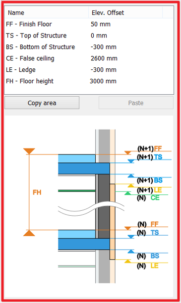
Parameters
- Finish Floor
- Top of Structure
- Bottom of Structure
- False Ceiling
- Ledge
- Floor height
Wall layers can be bound to the levels. The new wall styles, combined with the parameters of the levels make the the accurate design of detailed buildings easy.
The wall styles, coordinated by the level parameters can be automatically used for elements, created at different height levels. This means that if the base elevation changes, the wall height updates to the changes automatically.
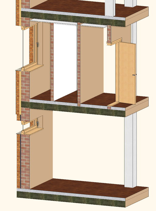
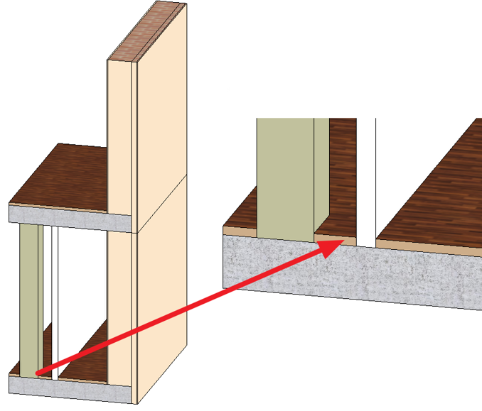
Wall Component Bounding
Wall styles coordinated by these story level parameters automatically apply to the elements created at different height levels. This means that if the floor height is changed, the wall heights will automatically follow the change.
Reshaping individual wall layers
In 2018 the same principles of reshaping can be applied to a single wall layer too.
Rule for Column-Slab, Wall-Slab intersection
Editing the front view profile of a curtain wall
By clicking on the Ribbon Bar / Curtain Wall / Edit Layout command or on the endpoint marker on the floor plan, you can edit the front view profile of the curtain wall with which the current profile can be further edited.
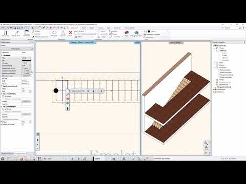
Editing the 2D stair symbol
You can change the appearance of the 2D symbol of the stairs to the schematic representation. In schematic mode, the components (lines, texts, etc.) are freely editable.
As a result of this command, the representation of the staircase switches to schematic representation on the floorplan, which is a freely editable group. Entering the group, the stair components (lines, texts, etc.) are freely editable. Editing does not affect the 3D model.
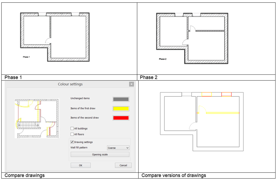
Dynamic Drawing Comparison
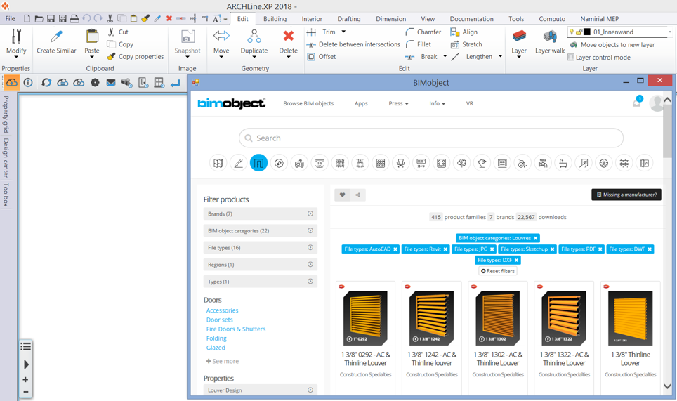
New international object libraries: BIMObject, Cadenas, Syncronia
The BIMObject, Cadenas, Syncronia are object libraries which contains BIM models of products of leading manufacturers.
The object catalogues above contains ten thousands of elements. From the international object libraries the content can be downloaded Revit RFA, SketchUp SKP and 3DS formats and the program creates native ARCHLine.XP elements from them. The BIM parameters saved in the RFA format are copied into the created ARCHLine. XP element.
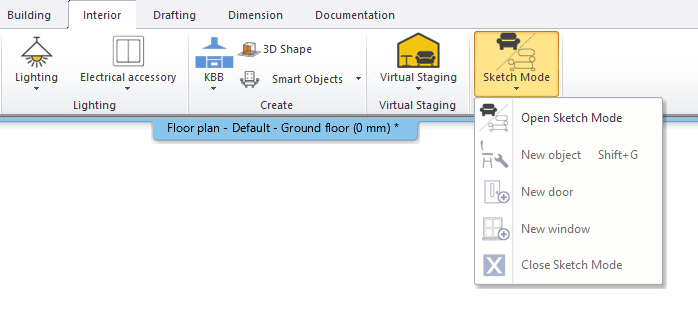
New ARCHLine.XP Sketch mode
The Sketch Mode allows to edit a selected object in a blank project. After starting this command the selected element is broken into its components which can be modified, deleted or a new material can be assigned to them individually. After the modifications the components should be saved as a new or replacement object, door or window. After this the Sketch Mode should be closed.
The main function of the Sketch Mode is to repair the errors of the objects downloaded from the internet but the objects already saved in the Design Center can also be modified in it easily.
When activating the Sketch Mode the program automatically saves the actual project and puts it into the background. In the Sketch Mode only the selected object is visible and editable. To return to the saved project close the Sketch Mode.
Location of the command: Interior – Sketch Mode – Open Sketch Mode
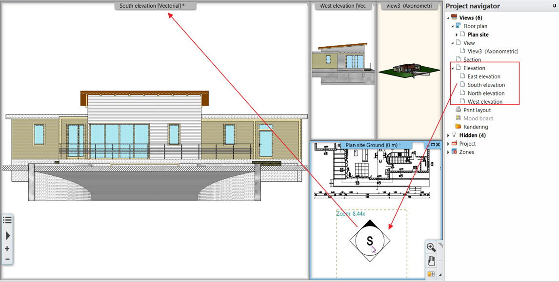
Elevation Views
You can create the model's exterior or interior elevation views from four predefined directions or other directions that you specify.
Factory build predefined directions are North, South, East and West.
You can place a reference elevation label on the floor plan clicking on the Elevation tag in the Project Navigator.
You can create additional exterior and interior elevation views.
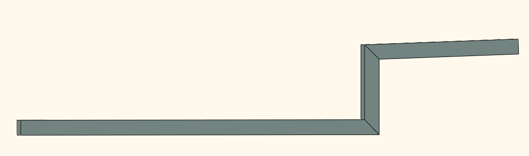
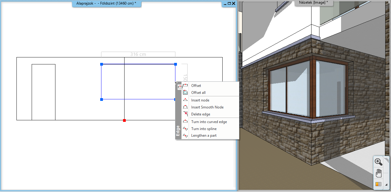
New Sweep Command
Sweep is extended with vertical section on floorplan and sloped section with slope angle definition.
Example: Sweep with 500 mm vertical section and 2% inclination on right side.
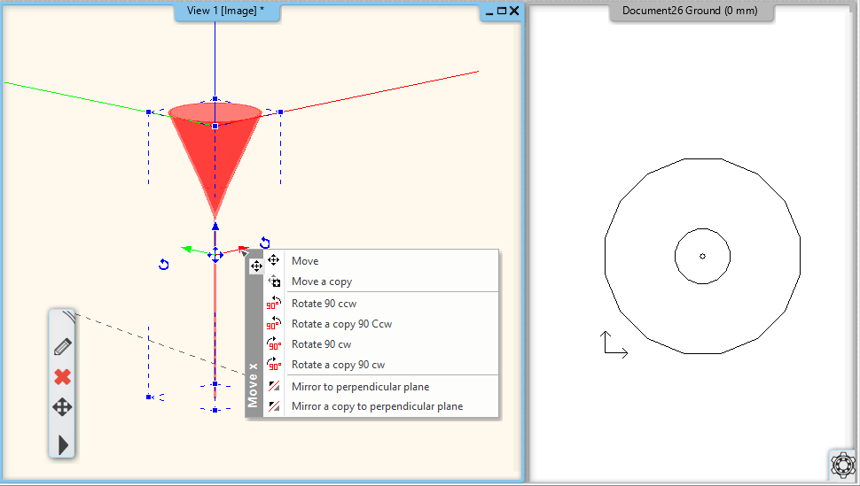
New basic 3D commands
The new rotating and mirroring commands make it easier to position the elements correctly. Geometric errors (eg.: upside down ceiling lights) which are frequently encountered in downloaded items can be corrected quickly with the new commands.
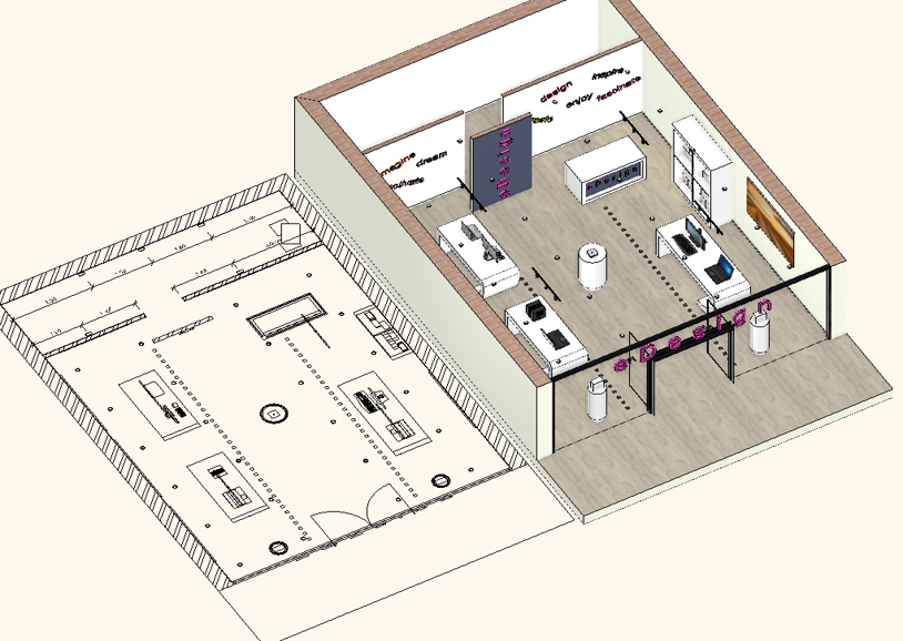
Add floor plan in 3D view
The command copies the floor plan to the 3D view at the same location as the 3D model. In 2018, you can move the floor plan to a more visible location than the model.
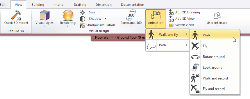
Virtual tour animation by capturing the walkthrough
The animation can be made not only by defining points in the 2D window, but in the 3D window you can walk through the model and by clicking with the left mouse button you can define points through which the walkthrough will be completed. Using this option you do not need to define the points on which the camera focuses from that specific point, when clicking with the left mouse button the program will create the animation based on the view in the 3D window. After the last point has been placed, you can close the command with the right mouse button, after which the path of the animation becomes immediately visible on the floor plan.
The command is available in the Ribbon Bar / View / Animation / Walk and Fly / Walk.
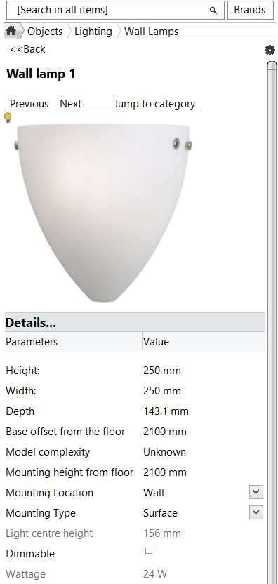
New Parameters for Lamps
Mounting height: For defining the height of mounting
Mounting location: Ceiling, wall, desktop, standing
Mounting type: Suspended, fixed on surface
Dimmable: Yes/No - is the lighting dimmable?
Wattage : Energy consumption index
Luminous flux: Accomulated Lumen value
BIM parameters: The above appear as BIM parameters, too
In ARCHLine.XPyou can set up whether the lamp is dimmable or not and you can also define the mounting height, location (Ceiling, Wall, Table, Standing) and type (Pendant or Surface) of the lamp. Setting up these BIM values will guarantee that even when you export the building into an IFC file the information about the lamp fixture won’t be lost.
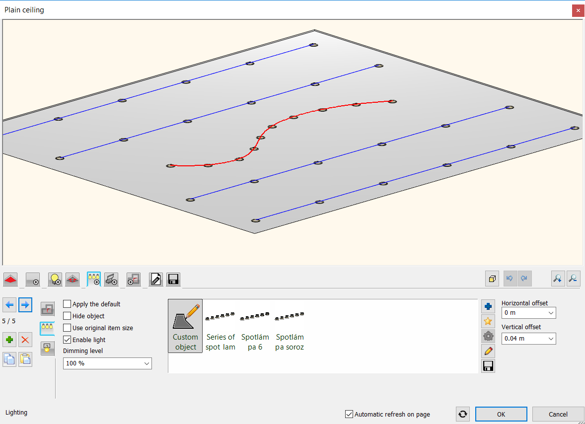
Recessed spot lamps
In ARCHLine.XP 2018 you can recess spot lamps into the false ceiling and cut the ceiling around them. This can be set on a new tab in the properties dialog of the false ceiling. A profile can be selected based on which the program creates the hole in the ceiling. The lamp groups can be turned on and off together and their brightness can be set as one.
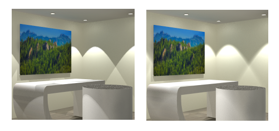
IES based spotlights
Rendering with more realistic IES based spot lamps
In ARCHLine 2018 the spot light cone linear intensity distribution is replaced with accurate IES light emission.
IES light emission provides physical photometric data distribution, in other words, it displays realistic light emission pattern.
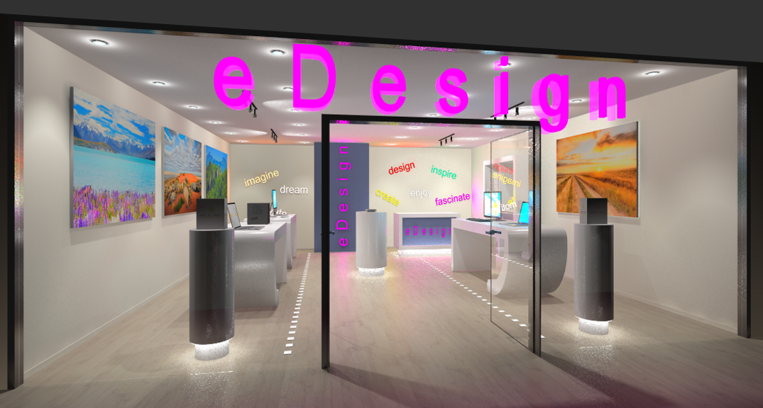
Lighting 3D text
Applies to external or indoor lighting, backlight with any color and brightness.
The 3D text can be easily edited.
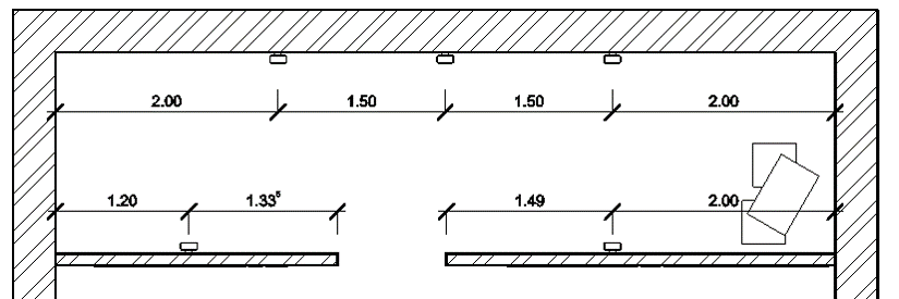
Lighting plan - lamp mounting dimensions
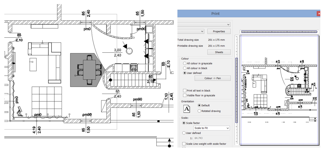
Wipeout - Creating a Blank Area to Mask Objects
A wipe-out object covers existing objects with a blank area. This area is turn off for plotting.
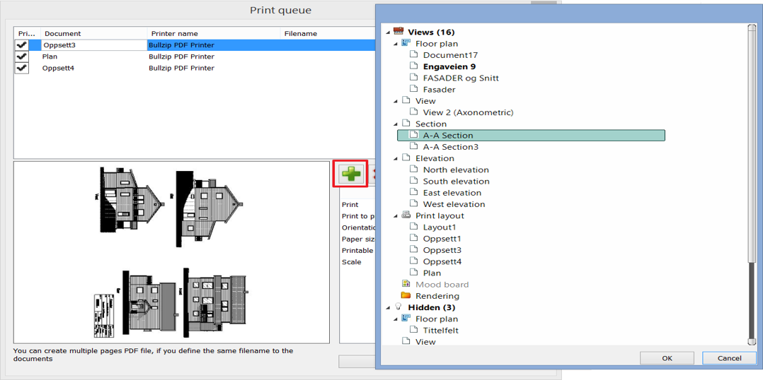
Enhanced Print Queue
New workflow is very simple and easy.
Print Queue management has changed and the new workflow is very simple and easy. Pressing the green plus button you can choose the next view to insert into the Print queue.