Case studies
Case Study: Alberto Betti, Omega Solutions
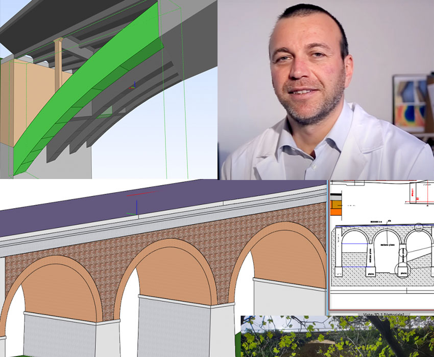
An interview with a Surveyor. Alberto Betti, freelancer and owner of Omega Solutions company, a service that was born from the merger of many years of experience gained in the sector of technical professions, technical-legal consultancy and building construction, together with specialized training in certified courses of high level. Read how they are using ARCHLine.XP.
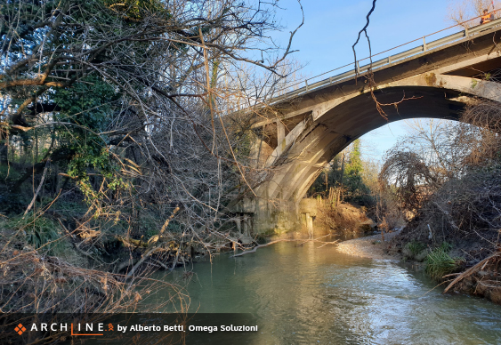
The company has been commissioned to carry out the execution of geometric-structural surveys, and technical-diagnostic investigations aimed at subsequent seismic tests, on some provincial road network infrastructures in Italy.
We are unable to disclose the client in this article because of privacy reasons, but we can emphasize that the order required the use of BIM and provided for the delivery of architectural survey models in IFC format, for subsequent structural calculation operations, of some bridges and viaducts.
After the on-site instrumental survey phases, detailed 2D drawings were produced containing all the measures necessary for the return of the models to be delivered.
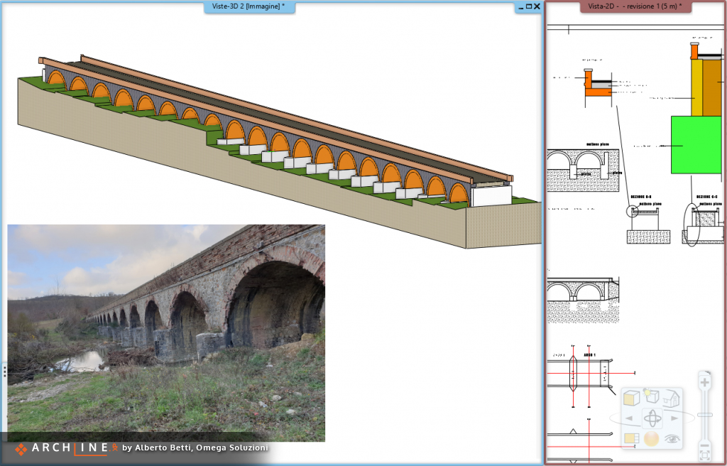
Thanks to the modeling capabilities of ARCHLine.XP, combined with careful analysis, it was possible to return perfect IFC models, with attention to detail, and containing many irregularities, inherent to the building heritage of the region.
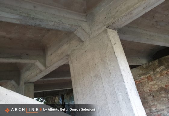
The major difficulties were the irregularities, and the complexities which were due to the fact that in many cases they were structures that over time have undergone more reinforcement or expansion interventions. When it comes to modeling regular elements, the operations are always quite easy, but in this case it was necessary to understand how to make the software do complex operations, and above all, with precise detail.
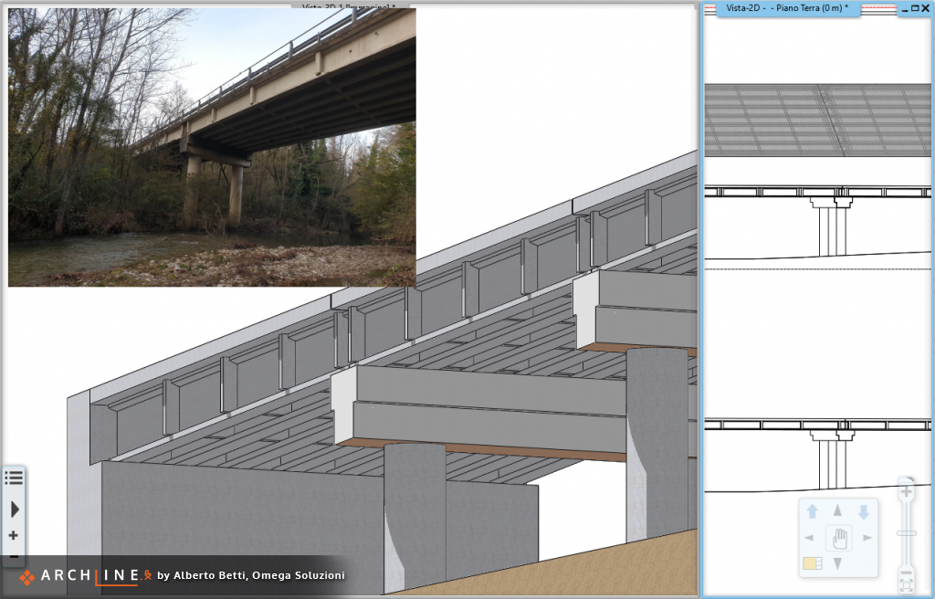
For example, one of the 20 bridges surveyed connected two road sections crossing the valley in a non-orthogonal way, but the sections were taken following the longitudinal profile to the road.
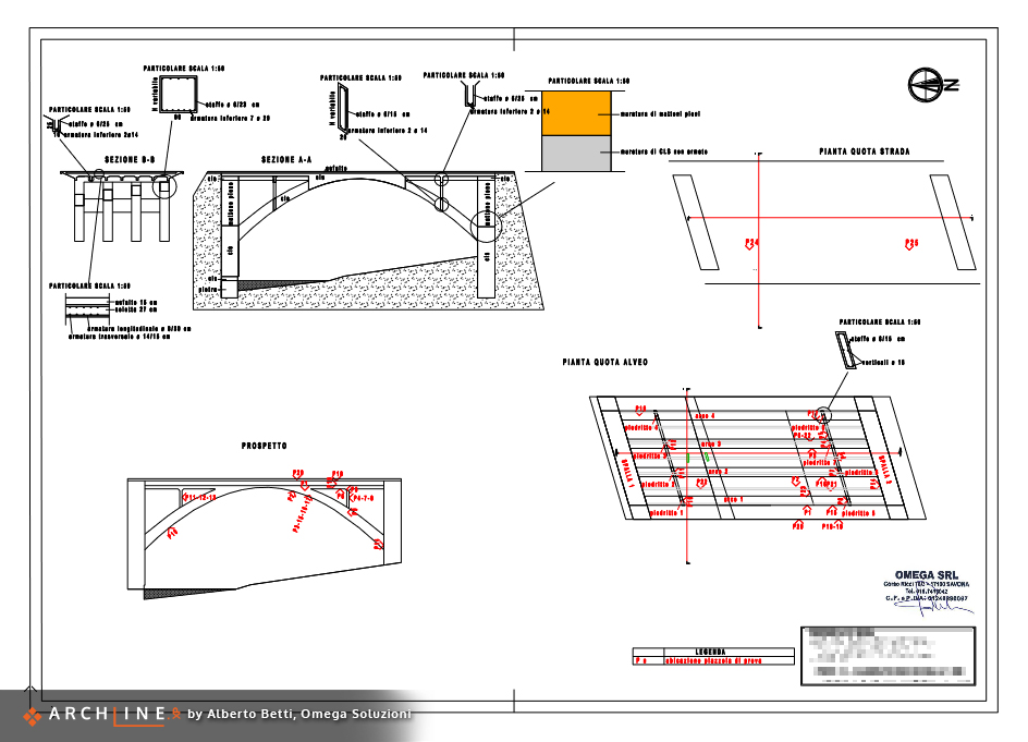
It was essential to be able to use advanced CAD tools to recreate the cross section, deriving it from the projection of the available one.
The "Scale on X axis" function which allowed to obtain the projection on an axis transversal to the direction of the valley.
In fact, many ARCHLine.XP commands - such as the wall command -support the definition of specific section a path. You can start from the cross section in the direction of the path, and then move the nodes of the shape to give it the inclined cut.
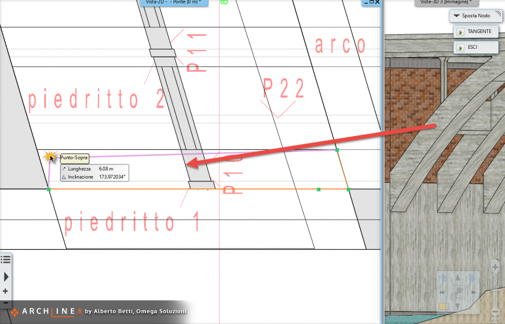
You can change the shape of the object using The "move node" command, while maintaining the changes to the profile.
The wall command proved to be very useful, and thanks to it, it was possible to model practically all the components, using the editing features of the 2D drawing.
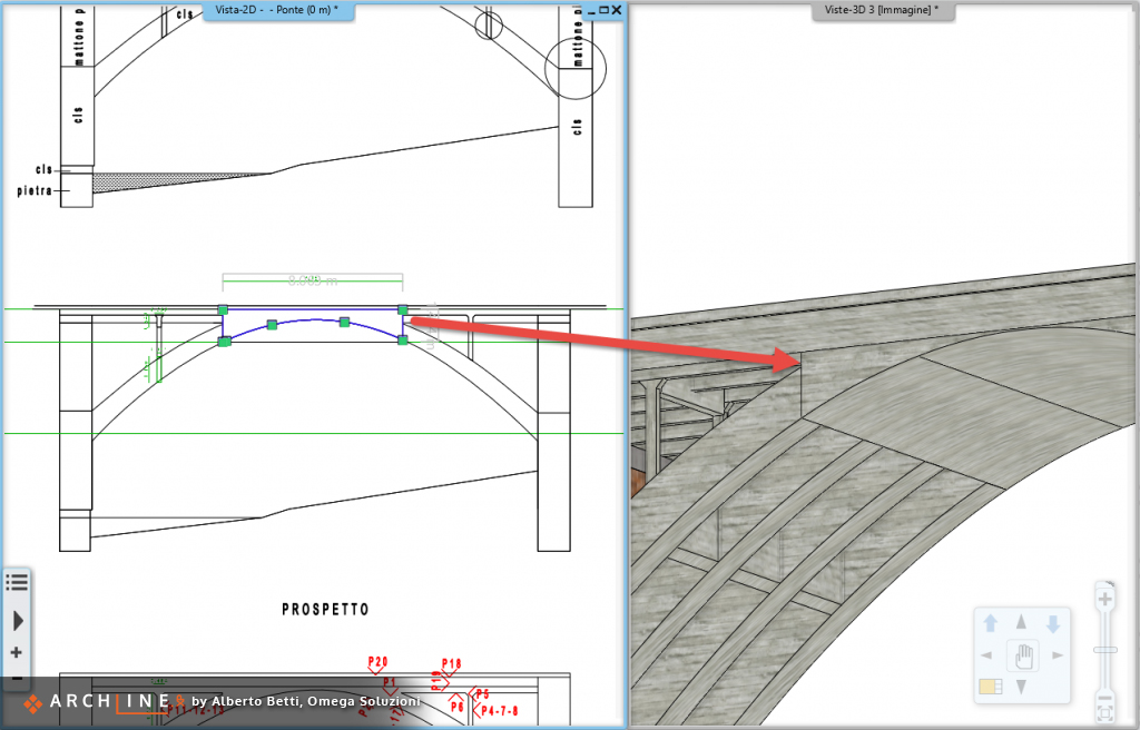
"The modification of the profile to shape the elements."
The 3D-view image, with the model placed in axonometry, was very useful to keep the evolution of the model under control, and in some cases it was a considerable time saver on some operations such as the "change elevation", which made it possible to move objects with snap precision, without having to measure every single elevation or height.
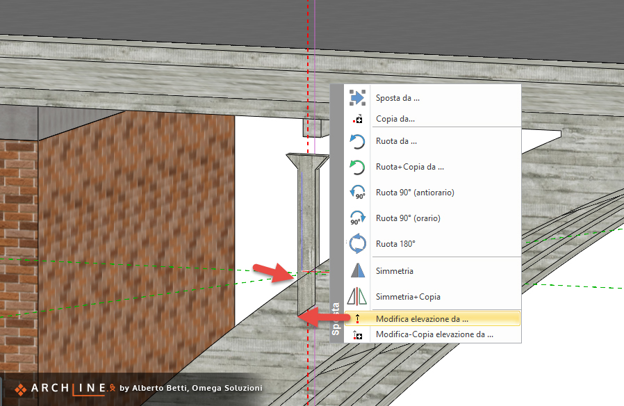 "Using the axonometric 3D view to precisely modify the elevation of the elements."
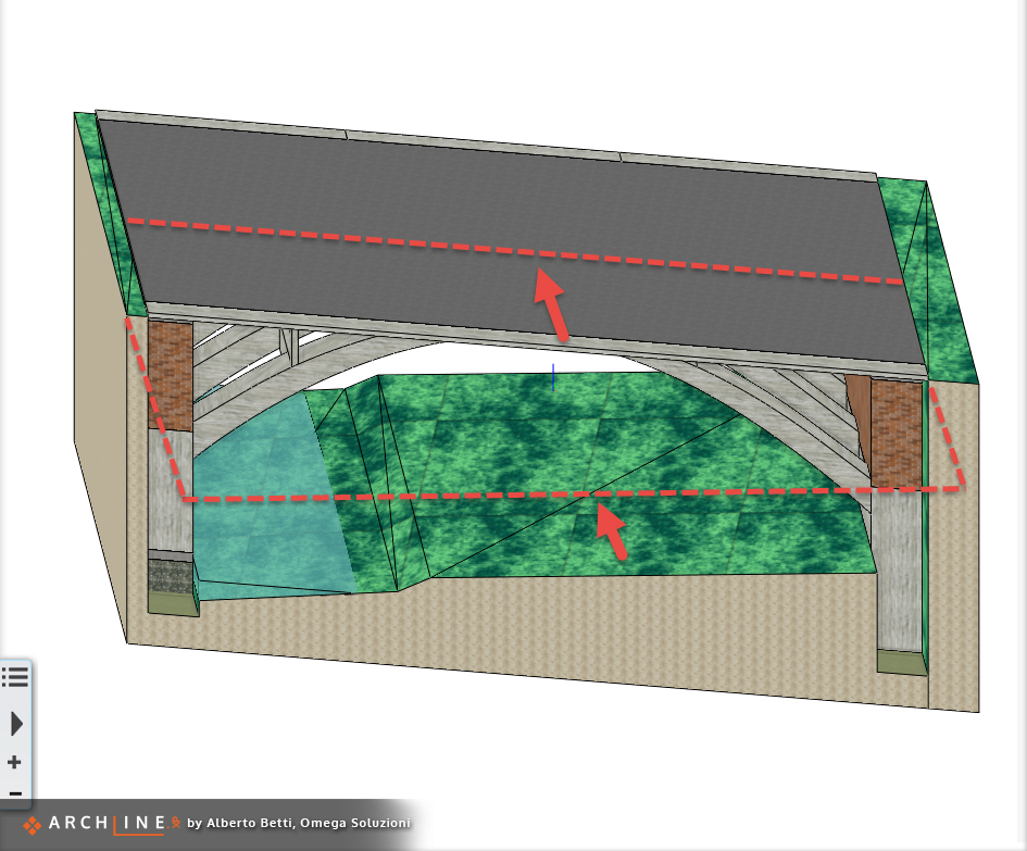
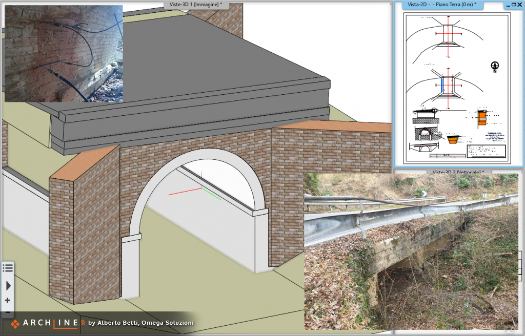
There is another trick we used in connection to the vectorial 3D view. It is a special way to see the 3D model, in fact this view allows you to work with all the advanced 2D CAD tools such as "Apparent intersection", or "Lock angle", which greatly help in defining the profiles of irregular structures, in which many times even the difference of a few centimeters compromises the overall development of the extrusion.
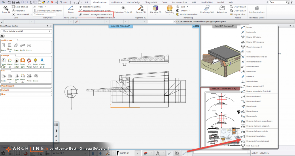
"The use of the vector 3D-view in frontal perspective to create complex profiles thanks to the CAD-2D tools."
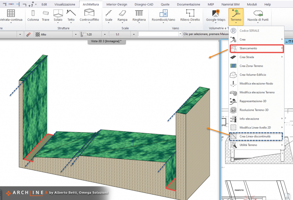
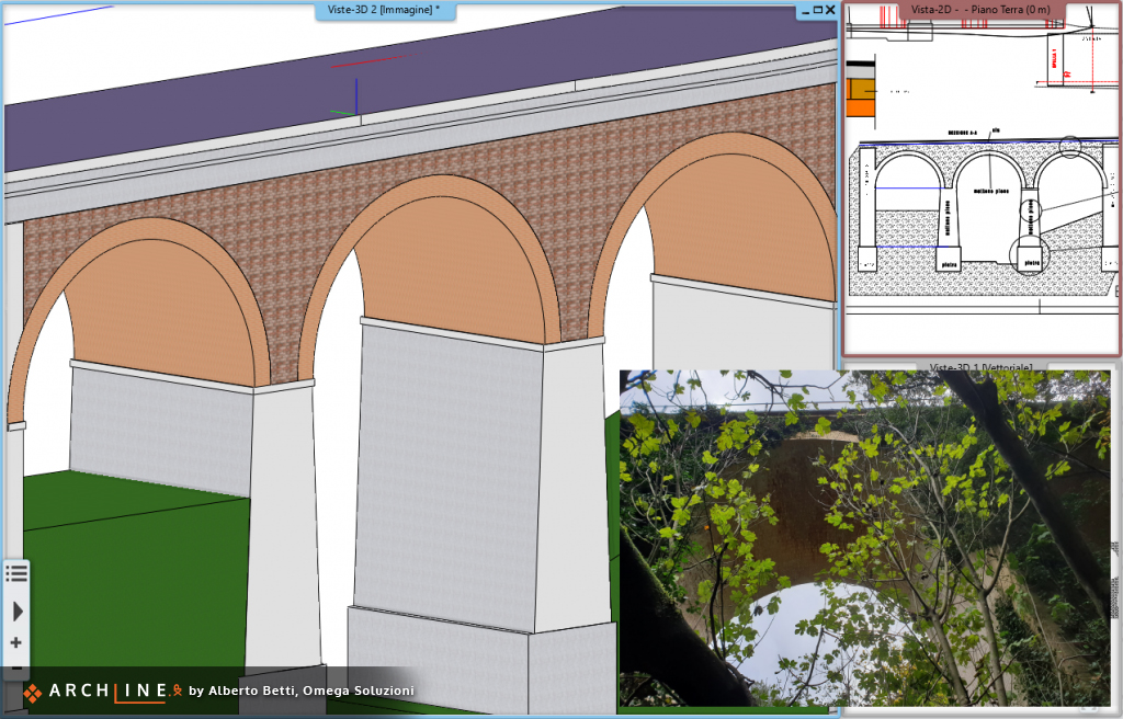
The terrain tool proved to be very useful for completing the models, in particular the "Plateau" and "Discontinuity lines" editing options made it possible to restore the context on which the structures were located in a simple way and with few measurements.
However, the modeling was not the only aspect, the delivery in fact provided for the creation of precise IFC models, in which each element was marked with its own IFC Type, in order to be read and managed by the structural software with which to manage the subsequent aspects regarding the project.
Fortunately, the flexibility of ARCHLine.XP provides the command that fits the best to the complexities in an easy way, and always provides the optionto assign IFC type witha a very simple technique: simply change it at the left hand side in the Property manager.
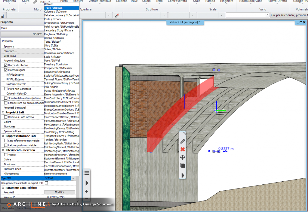 "The assignment of the IFC Beam Type to an element modeled with the "Wall" tool."
The delivery not require to fill informations, but only the 3D model.
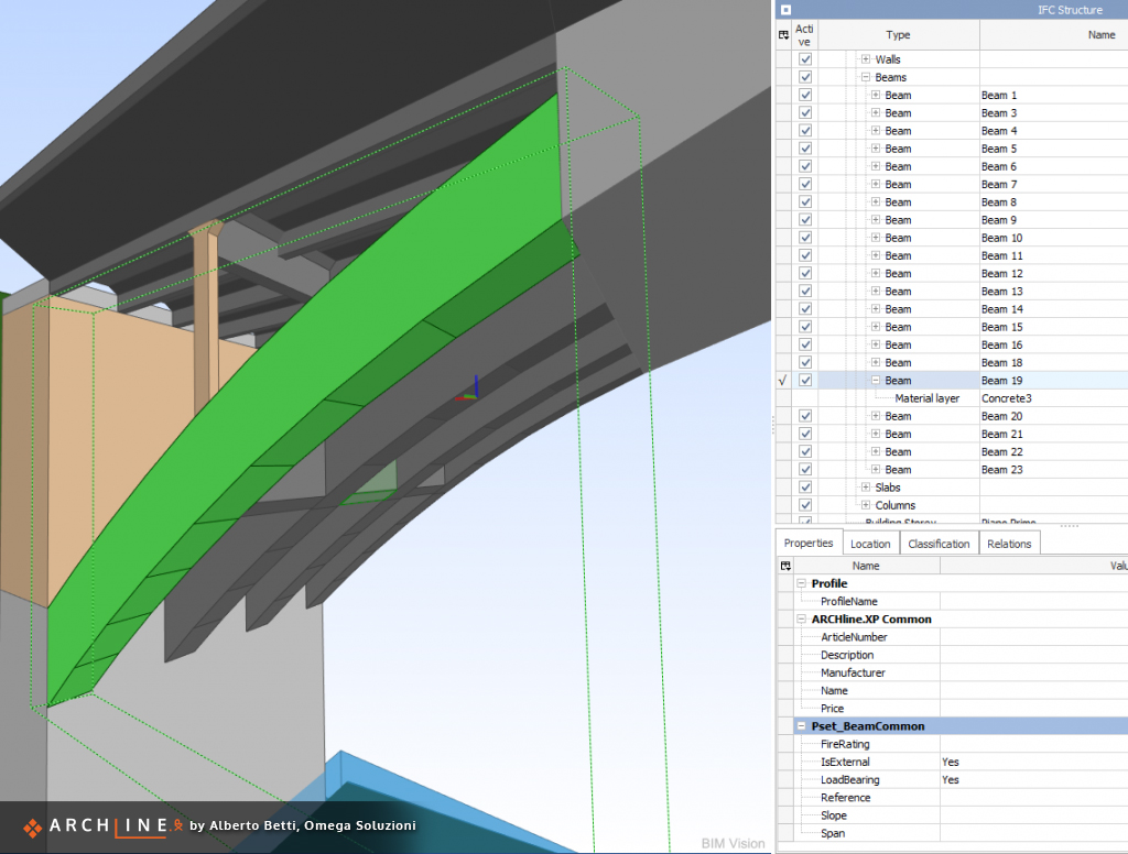 The IFC model opened in a third-party viewer application. The selected element is a beam.
ARCHLine.XP is a powerful and flexible tool, able to adapt even to those needs that differ from the design of new buildings, and also thanks to the collaboration with the Cadline Software technical staff of Padua - a team of professionals able to "speak the same language "and to understand the needs - we were able to complete the project in the ways and times set.