Professional articles | Blog | ARCHLine.XP
10 tips to create beautiful drawings in ARCHLine.XP
In this article, we've collected 10 tips to make the drawings in the documentation more beautiful. Let's see what to do to create perfect drawings!

1. Line thickness
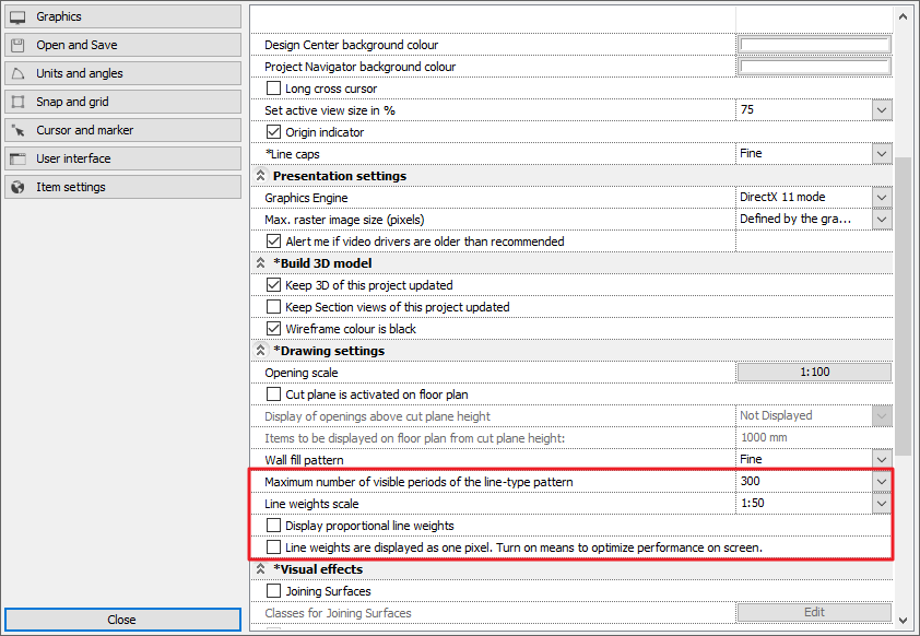
A beautiful drawing is based on the correct setting of line thickness values. You can access the global settings of line thickness by clicking on the cogwheel icon in the bottom left corner and navigating to the Display tab. Here you can set the scale of the line thickness display or turn off the display completely during work. It is important to know that regardless of this, the line thickness you set will be displayed on the printed document.
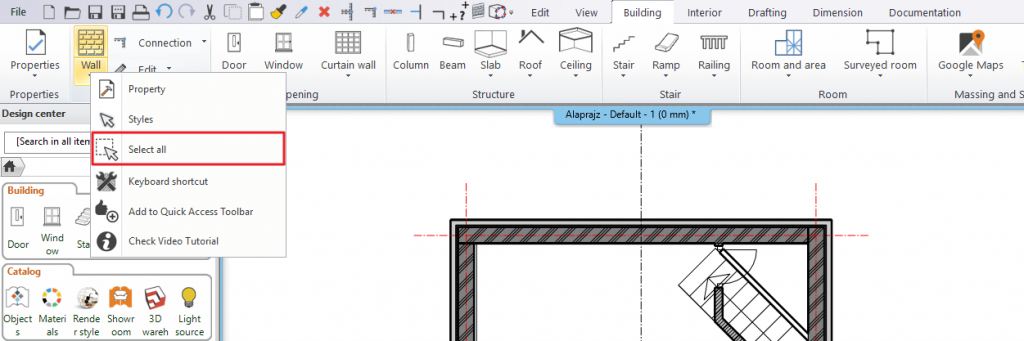
Set the thickness of the walls in the plan in one step. On the Ribbon Bar, right-click on the Wall command and choose the Select All command.
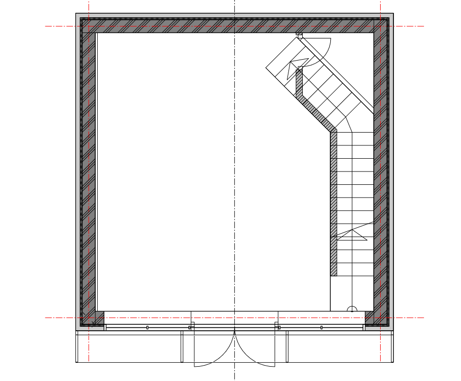
Then, on the left side on the Properties tab, set the line thickness to 0.4 mm.
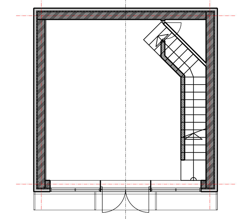
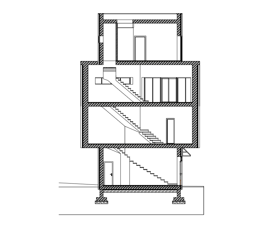
The line thickness should also be set when creating a section. You can do this in the section properties dialog, moreover, you can select the item types to which you would like to apply the settings.
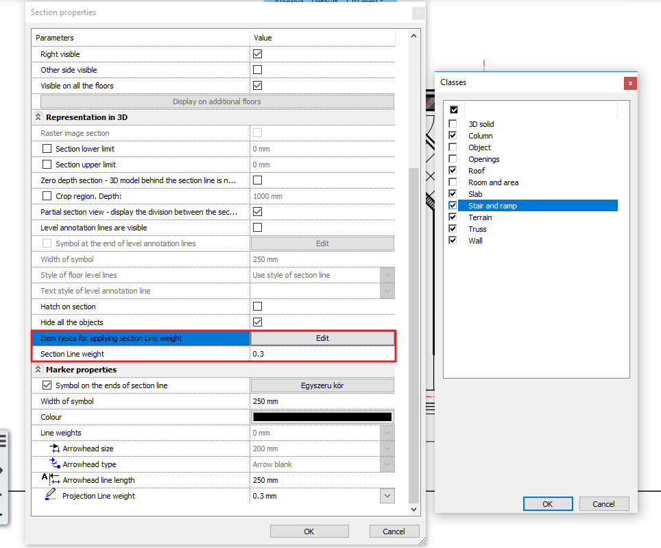
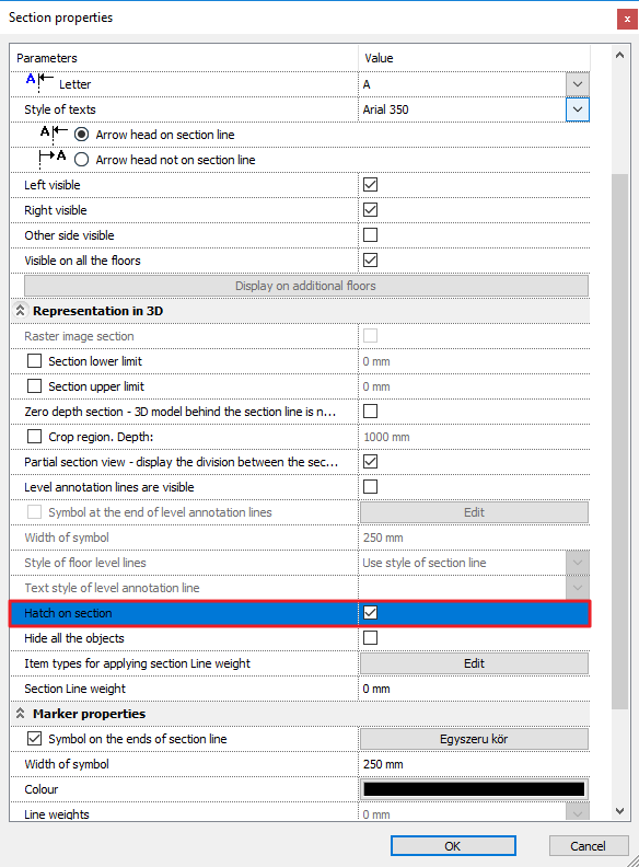
In this same dialog, you have the ability to turn on the hatch of the section. The hatch of an item is based on the properties of the item.
2. Anti-aliasing
When lines are displayed at an angle on the drawing and they appear pixelated. This is what anti-aliasing can solve. In ARCHline.XP, this option is automatically enabled: you can turn the option on / off by clicking on the Properties tab, while nothing is selected and you are not currently performing a command.
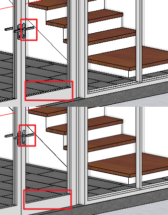
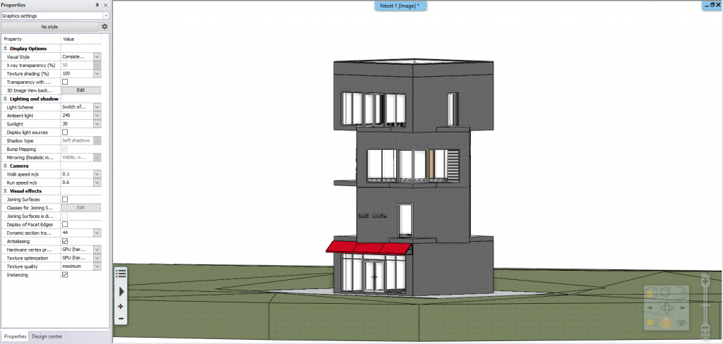
3. Joining surfaces
With the same method, you can access the Joining surfaces option switch on the Properties tab. This is useful when you want surfaces with the same material to be displayed as one surface. With this option, you can remove lines between the slab and the wall or even two joining walls. Using this option results in clearer drawings. It is important to know: On rendered images, the borderline of surfaces of the same material will not be visible even if the Joining surfaces option is off.
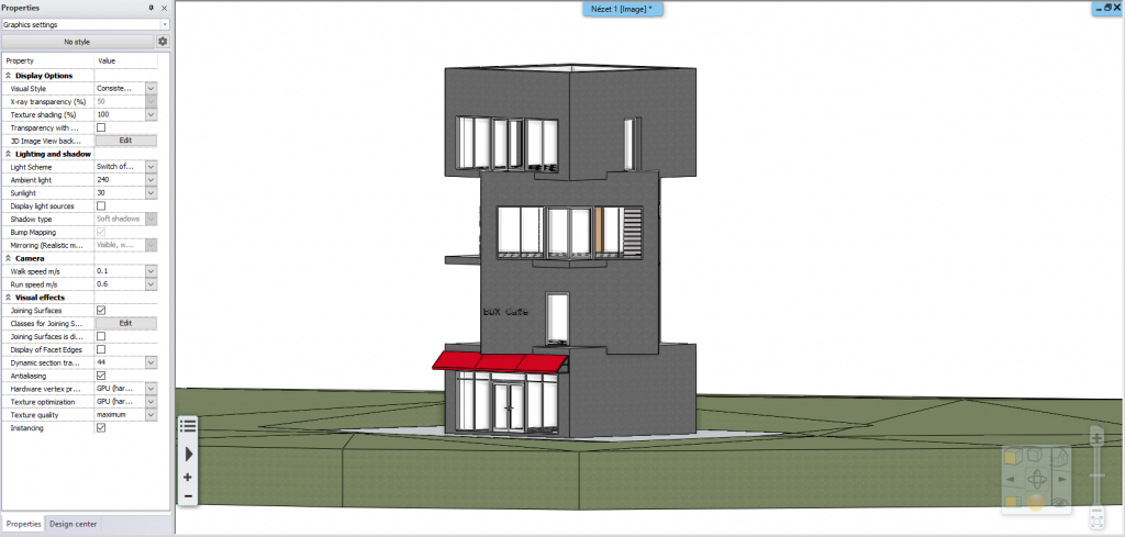
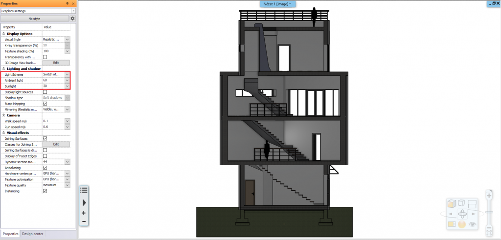
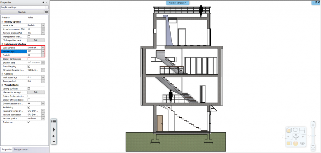
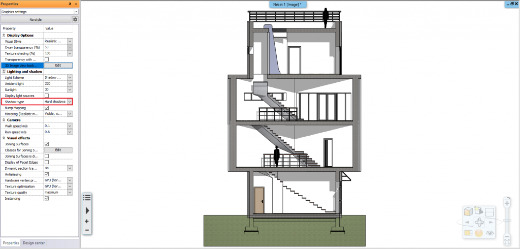
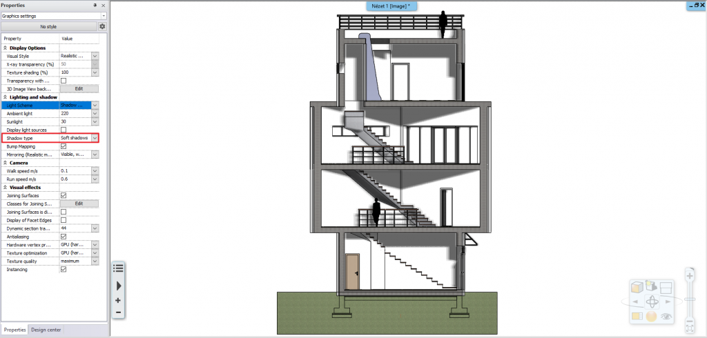
4. Ambient light, sunlight settings, hard shadow, soft shadow
If the 3D window is active and there is nothing selected or you are not currently performing a command, you can set the natural or artificial light effects on the Properties tab. You can choose to turn off all light effects on the drawing, use only artificial or natural lights, or both. When you choose a setting that shows shadows, you can set the shadow to be hard or soft. You can also change the ambient light and sunlight to control how much light your model is exposed to.
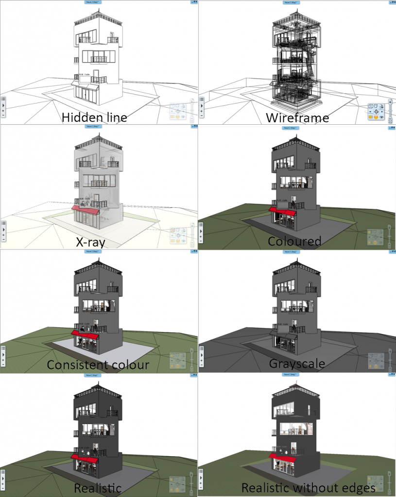
5. 3D visual styles
ARCHLine.XP allows you to use from a set of 8 different 3D visual styles. Different cases require different representation modes. As a designer, you can set these to present your design in the best possible method. The two most commonly used ones are Consistent colour and Realistic. When using Consistent colour the surfaces with the texture or colour applied to them appear without shades and light effects, giving the entire surface a homogenous effect. In Realistic display mode, the materials are more similar to their final rendered image, with shadows and reflections
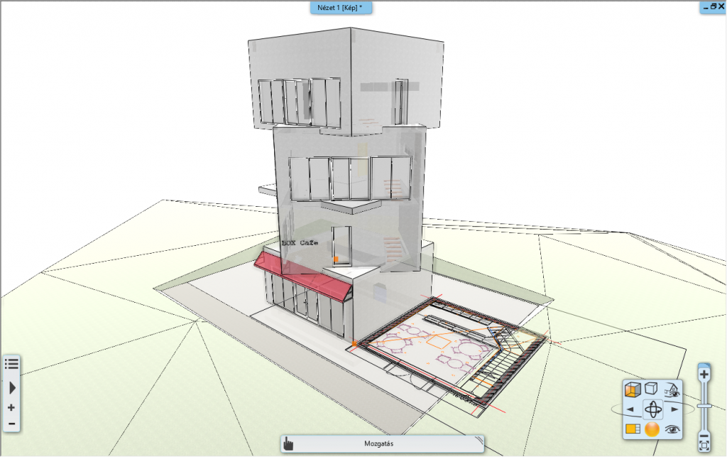
6. Floor plan under the 3D model
We can achieve spectacular results by displaying the floor plan under the 3D model. You can turn this option on and off on the Ribbon Bar, View tab, Visual styles group. The floor plan is displayed as a standalone element in 3D, so you can easily move around and place it next to the model.
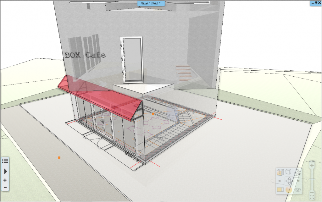
7. Cut-away 3D model
Using the Cut-away 3D model tool, you can draw a square on the floorplan around the elements you want to display in 3D. After this, the architectural elements, objects etc. are cut off along an invisible plane and isolated in the 3D view, giving you the opportunity to discover the details of the model, display connections that otherwise would not be visible. By using the views, you can even set up the model imitating a section, with materials and shadows, and then save the image using the Snapshot command on the Documentation tab. The picture can be used later in the documentation or for intermediate presentation purposes.
Cut-away 3D command remembers the scope box. (from 2019 Build 323)
You can add unlimited number of Cut-away 3D boxes to floor plan to memorize precisely 3D partial views. Clicking on the box's marker icons repeat the Cut-away 3D command on active floor or all floors. Entering into the group that represents the box you can edit the box profile freely. Useful for projects with a lot of details.
8. Shadows in the cut away 3D model
The cut away 3D model is perfect for shadow display using the previously learned way. All you have to do is select the Realistic display mode and turn on the light effect and shadowing on the Properties tab. Then, on the Ribbon Bar, View tab, you must start the Shadow Simulation command. In the dialog that appears, use the time and date slider to set a time when the lights will illuminate the model best.

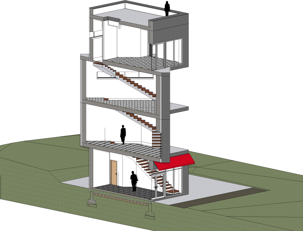
9. Human shapes on 3D view
When you create 3D model, you can place human shapes to illustrate the sizes. Place human shapes from the Design Center. When you specify the Cut-away 3D box in the floor plan and it includes the human shapes, they will appear in the 3D view.
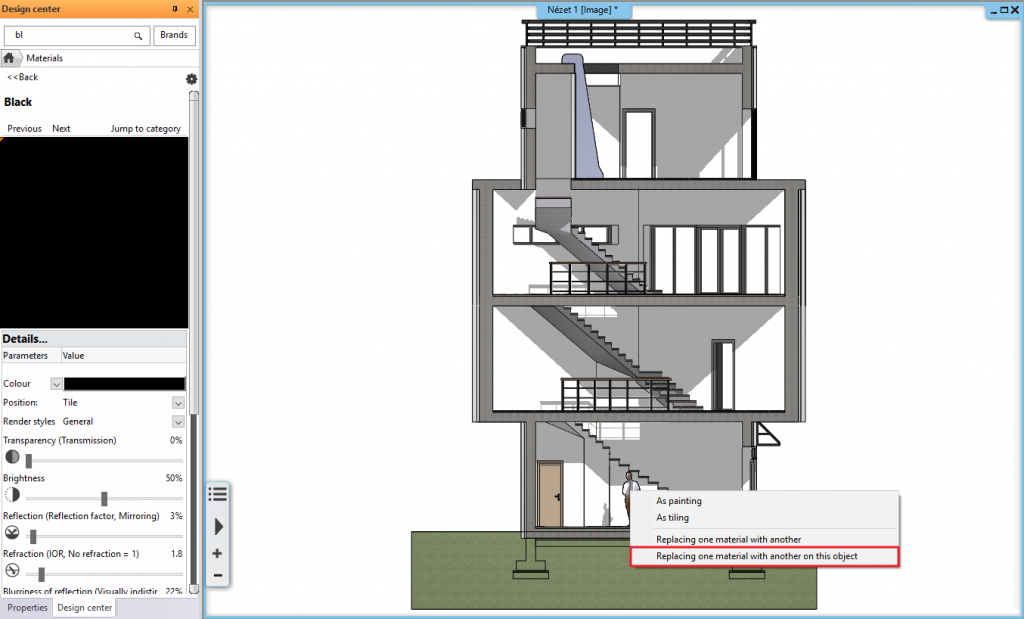
If you want to color them instead of texture, select the Black color to replace the texture of the human face and turn on the hatch property.
Specify the color or hatch on the section of the human face to which this material is assigned.
Regenerating the model with the Cut-away 3D command we can easily access elements that are difficult to select in entire 3D model.
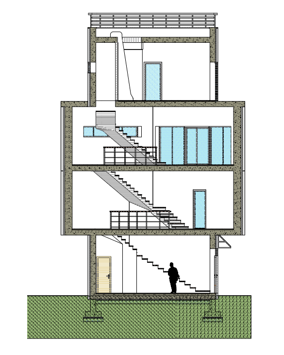
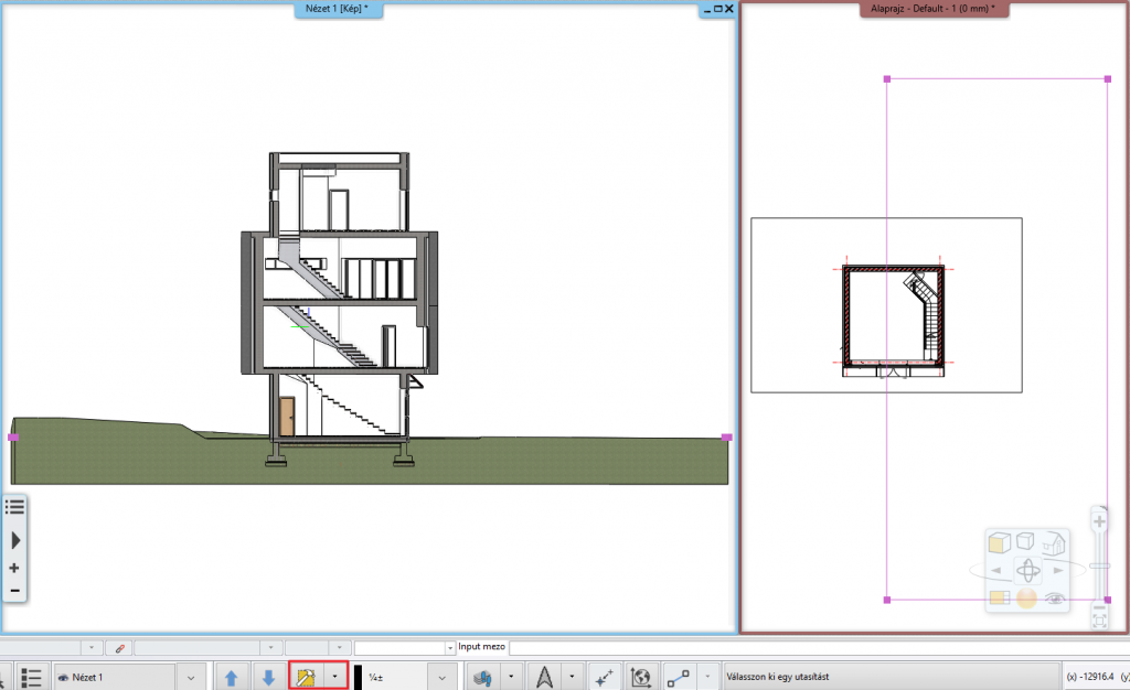
10. Human shapes on section
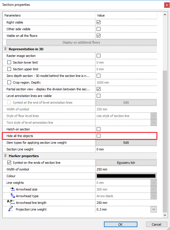
If you only want to display human figures on section without any other objects, put them on separate layer and turn off layers with other objects before making section view. Switch off the Hide all the Objects option in the section properties dialog.
The section is usually displayed in Hidden line mode, so the shape on it is just a contour.
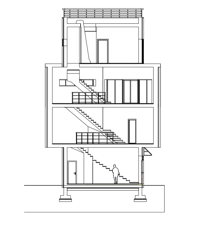
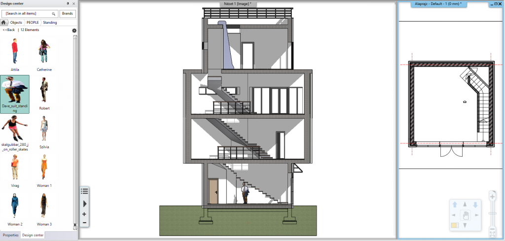
Select the Black material with which you have replaced the texture of the human shape previously and switch on its Hatch in 3D properties. Specify the fill color this material will appear on a section .
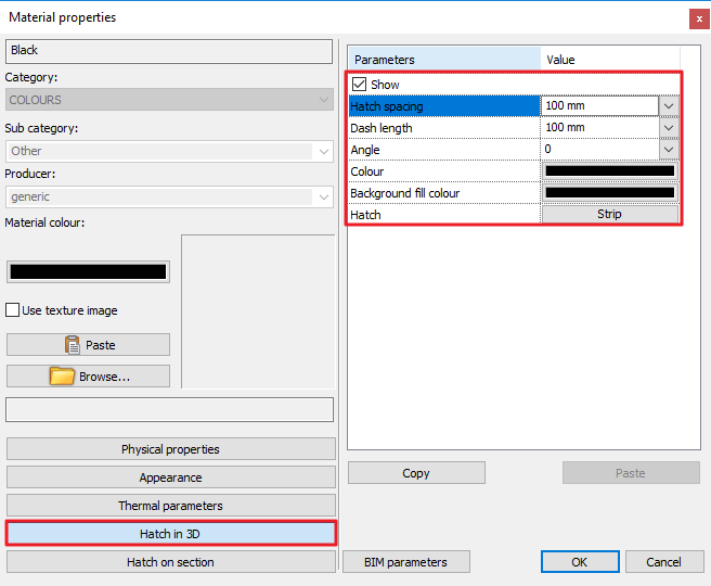
Return to the section view and choose Realistic representation, the humans shape appears with black fill.